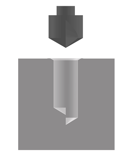
Installation Procedure

CoilThread inserts are designed to be installed into precut STI (ScrewThread Insert) threads. The installed insert will provide a finished thread meeting the requirements of FED-STD-H28. Example: An 8-32 insert installed into an 8-32 STI 3B thread will create a standard 8-32 UNC 3B thread profile.

A proper STI thread is paramount to creating a precise finished thread profile. KATO recommends the following procedure to ensure the best installation and function of a CoilThread insert.

Step 1: Drill

Step 1: Drilling

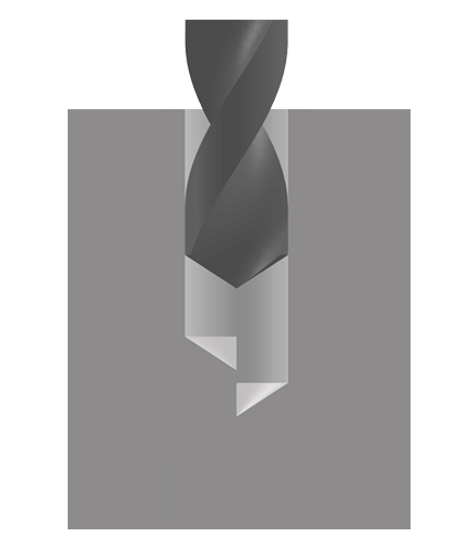
CoilThread Inserts are designed to be installed into thread profiles which conform to NASM33537 (Assembly and thread dimension specification). Using the proper drill size will ensure the Minor Ø of the STI thread will be within spec. The suggested drill will depend on the size of the STI thread being created and the parent material. A full table can be found in KATOpedia under Drill & Tap Dimensions. The table includes the range for the Minor Ø as well as the minimum drilling depth to accommodate the installed insert (minimum drilling depth is dependent on the type of STI tap being used).

It is preferred practice to drill as close to the maximum allowable value for the Minor Ø if additional drill sizes are available. KATO has found this eases installation, prolongs the life of the installation tool, and has a negligible effect on the strength of the fastener assembly.

Step 2: Countersink

Step 2: Countersink

KATO recommends countersinking a hole where allowable. Countersinking facilitates the installation of an inserts by providing a lead for the first thread. NASM33537 requires a countersink to be 120°±5°. The diameter of the countersink is dependent on the nominal size of the STI thread being created. A full table can be found in KATOpedia under Drill & Tap Dimensions.

Step 3: Tap

Step 3: Tap

CoilThread Inserts do not have a Class of Fit associated with them. CoilThread Inserts conform to the thread profile created by the STI tap. Whatever the Class of Fit of the STI tap (3B, 2B - Unified; 4H, 5H - Metric) is the Class of Fit of the finished thread profile after insert installation. It is recommended to use KATO STI cutting taps as opposed to thread forming taps (why?).

Visit KATOpedia (Drill & Tap Dimensions) for an extensive list of tapping depths. The tapping depths given are the minimum full thread values. These should be noted as such when designing or reading a print.

Step 4: Gage

Step 4: Gage

It is very important step to verify the dimensions of the STI threads before attempting insert installation (Why Gaging Matters?). KATO recommends gaging the Minor Ø with a graduated pin gage set; the Pitch Ø and the Major Ø with a Go/NoGo STI gage. Gaging should be repeated after any finish or plating is applied to the STI threads. Any platings/coatings can drastically affect installation and internal thread dimensions (Learn More).

NASM33537 states "Accuracy of the finished thread, when the insert is installed, is dependent upon the accuracy of the tapped hole. If the finished tapped hole gages satisfactorily, the installed insert will be within the thread tolerance when the insert meets the drawing requirements. It is, therefore, not necessary to gage the installed insert. After the insert is installed, the GO thread plug gage may not enter freely because the insert may not have been fully seated in the tapped hole; however, the insert should become seated after a bolt or screw is installed and tightened." In addition, it is not possible to gage a locking insert.

Step 5: Install

Step 5: Install

Follow the instructions accompanying the installation tool for proper insert installation. If additional copies of the instructions are needed please visit KATOpedia (instructions). Insert installation depth is dependent on the presence of a countersink (3/4 to 1-1/2 turns below the surface with a countersink and 1/4 to 1/2 turns below the surface without a countersink).

  • Tangless CoilThread Insert installation is now complete.
  • Tanged inserts require removal and retrieval of the tang, continue to step 6.

Step 6: Tang Break-Off

Step 6: Tang Break-Off

KATO recommends the tang always be removed to ensure that the full threads of the bolt fully engage the locking coils (when using locking inserts). To achieve maximum assembly strength the bolt must engage the entire insert length. Use the KATO Tang Break-off Tool to ensure accurate and clean tang break off. In blind holes it may be necessary to remove the broken tang from the bottom of the hole (recommended).


If you have any questions please view our Hole Preparation Guide which can be found in KATOpedia (instructions) or contact the KATO Support.

Feedback

Your feedback is important to us! Receive your complimentary gift.

Take Survey